Raspberry Pi 4 - Multiple SPIs
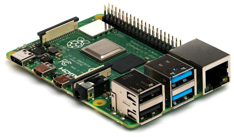
In this post I want to talk about the new Raspberry Pi 4 (RPI4) and one of its new features: Multiple (up to 6) accessible SPIs! While the older RPIs all had SPI0, SPI1 and SPI2, only SPI0 and SPI1 where accessible through the pin headers. Now there are SPI3 through SPI6 in addition to that!
I'll assume you know your way around the command line and that you know what SPI is. For an explanation of what I'm doing here, what a device tree and an overlay is, read the article about the Device Tree.
SPI Overlays
To use any interface on the hardware pins, the desired interface has to be enabled first. This can be done by adding the corresponding line to /boot/config.txt and rebooting the RPI. For SPI this is:
dtoverlay=spi<n>-<m>csReplace <n> with the SPI bus number you want to use. Values: 0-6
Replace <m> with the amount of chip selects (CS) you want to enable. Values: 1-2
There's one exception for SPI0: here <m> is empty ( dtoverlay=spi0-cs ). This enables two chip selects automatically.
If you want to use pins that are different from the default chip select you can add parameters at the end of the line. Here you can also enable/disable spidev. This creates a user interface node to access the bus e.g. via python. It's on by default.
For example to enable SPI6 with 2 CS lines on GPIO16 and GPIO26 you have to add the following line to /boot/config.txt:
dtoverlay=spi6-2cs,cs0_pin=16,cs1_pin=26Be careful, lines must be shorter than 80 characters. If a line becomes to long you can use the equivalent long form:
dtoverlay=spi6-2cs
dtparameter=cs0_pin=16
dtparameter=cs1_pin=26
Additionally disable spidev:
dtoverlay=spi6-2cs
dtparameter=cs0_pin=16,cs0_spidev=disable
dtparameter=cs1_pin=26,cs1_spidev=disable
Enabling all SPI busses at the same time does not work by default, because some of the chip select pins overlap other SPIs and cause conflicts (e.g. on hardware pin 26 [GPIO7] below SPI1 CS1 and SPI4 SCLK share the same pin). To prevent this you have to use CS pins that are different from the default.
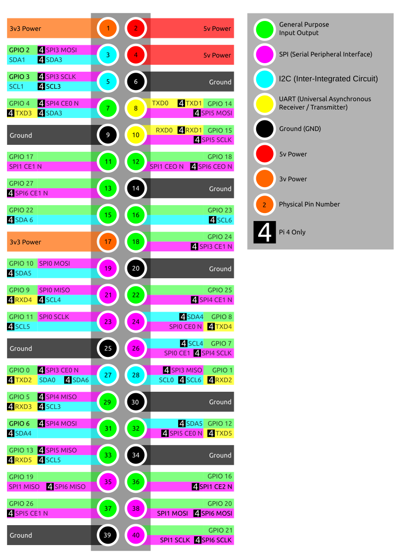
Keep in mind that there's a difference between the hardware pin number and the GPIO pin number. Also notice that SPI1 and SPI6 use the same pins and can therefore not be enabled at the same time.
The SPI pins (other than CS, i.e. MOSI, MISO, SCLK) are bound by hardware and cannot be changed.
Useful Commands
dtoverlay
So far so good, but rebooting the PI every time to make a change is really annoying, especially if you're just trying out different configurations. While the above is perfect for persistent setups, there is a way to temporarily load an overlay. Using the example from above:
pi@raspberrypi:~ $ dtoverlay spi6-2cs cs0_pin=16 cs1_pin=26This will not persist a reboot though. To remove it again use the following command, only specifying the name of the overlay:
pi@raspberrypi:~ $ dtoverlay -r spi6-2csWith dtoverlay -h you get a nice help text of the program. It's a very useful program, as it can also give you a list of available overlays, currently loaded overlays, etc.
dtparam
The dtparam program is only for parameters directly to the base device tree. For overlays (like the SPI above) always use dtoverlay with a list of parameters.
raspi-gpio
To check if the overlay was applied correctly and the pins have been configured properly you can check the output of
pi@raspberrypi:~ $ raspi-gpio getThis should contain something like the following if you enabled SPI6 like above
[...]
GPIO 19: level=0 fsel=7 alt=3 func=SPI6_MISO pull=DOWN
GPIO 20: level=0 fsel=7 alt=3 func=SPI6_MOSI pull=DOWN
GPIO 21: level=0 fsel=7 alt=3 func=SPI6_SCLK pull=DOWN
[...]
GPIO 16: level=1 fsel=1 func=OUTPUT pull=DOWN
[...]
GPIO 26: level=1 fsel=1 func=OUTPUT pull=DOWN
[...]
Outlook
More CS pins
Enabling and disabling SPI busses is nice, but with the default overlays you are mostly limited to 1 or 2 CS. There are a lot of tutorials on how to use a separate multiplexer chip to achieve more, but since any GPIO pin can be used you can theoretically have a lot of CS pins before running out options. Unfortunately this is not possible with the currently available overlays, but fret not: You can edit them to support more.
Other SPI devices (CAN, ADC, ...)
But what if you have a device that connects through SPI like the MCP2515 CAN bus chip or the MCP3008 10bit ADC? There are existing overlays for that, but unfortunately for most of them have been written only for SPI0 and will not work on any other of the new SPI interfaces or even have fixed interrupt/cs pins. To get those devices to work on a different SPI bus we need to edit the device tree overlays ourselves. For a way to do that read the article on Device Trees.
Cover Image by Michael Henzler / Wikimedia Commons
